Article Text

Abstract
Background Endovascular treatment of paraclinoid aneurysms is preferred in clinical practice. Flow alterations caused by stents and coils may affect treatment outcome.
Objective To assess hemodynamic changes following stent-assisted coil embolization (SACE) in subtotally embolized paraclinoid aneurysms with residual necks that were predisposed to recanalization.
Methods We studied 27 paraclinoid aneurysms (seven recanalized and 20 stable) treated with coils and Enterprise stents. Computational fluid dynamic simulations were performed on patient-specific aneurysm geometries using virtual stenting and porous media technology.
Results After stent placement in 27 cases, aneurysm flow velocity decreased significantly, the reduction gradually increasing from the neck plane (11.9%), to the residual neck (12.3%), to the aneurysm dome (16.3%). Subsequent coil embolization was performed after stent placement and the hemodynamic factors decreased further and significantly at all aneurysm regions except the neck plane. In a comparison of recanalized and stable cases, univariate analysis showed no significant differences in any parameter before treatment. After stent-assisted coiling, only the reduction in area-averaged velocity at the neck plane differed significantly between recanalized (8.1%) and stable cases (20.5%) (p=0.016).
Conclusions Aneurysm flow velocity can be significantly decreased by stent placement and coil embolization. However, hemodynamics at the aneurysm neck plane is less sensitive to coils. Significant reduction in flow velocity at the neck plane may be an important factor in preventing recanalization of paraclinoid aneurysms after subtotal SACE.
- Aneurysm
- Blood Flow
- Stent
Statistics from Altmetric.com
Introduction
Stent-assisted coil embolization (SACE) has been widely used in the treatment of intracranial aneurysms (IAs). The recanalization rate of IAs following SACE has been reported to be 8.1–12%.1 ,2 Incomplete initial embolization is considered an important factor in predicting recanalization;3 however, progressive thrombosis after subtotal initial embolization with residual necks can be found at angiographic follow-up,2 and the underlying hemodynamic mechanisms are not totally understood.
Hemodynamic effects have been shown to have a significant influence on recanalization of an aneurysm following embolization with coils alone,4 ,5 and some researchers have demonstrated that the placement of intracranial stents may change the hemodynamic characteristics of IAs.6 However, the relationship between hemodynamics and treatment outcome following SACE has received less attention. An advanced understanding of the hemodynamic effect in the occlusion process may lead to optimization of outcomes.
Hence, in this study, we focused on a well-defined subgroup of IAs (subtotally embolized paraclinoid aneurysms) to characterize hemodynamic alterations in those aneurysms that were predisposed to recanalization after SACE. This study design minimized the influence of other factors on hemodynamics, such as location and aneurysm type (bifurcation aneurysms and sidewall aneurysms). Because surgical clipping of paraclinoid aneurysms is challenging, SACE of such aneurysms is preferred in clinical practice.7 ,8 Nevertheless, recurrence remains a problem. Therefore, we chose paraclinoid aneurysms for investigation.
We used new computational methods in this study. For intracranial stenting, a new patient-specific virtual stenting workflow, which would more accurately reflect actual stent deployment, was used to perform in vivo stent deployment. On the other hand, The porous media method was used for simulation of coil mass, which may reflect the real situation more accurately, creating more valid results. We also evaluated the hemodynamic alterations in each aneurysm at three different regions (aneurysm neck plane, residual neck, and aneurysm dome) during the procedure (before treatment, after stent deployment, and at the end of SACE), to demonstrate the hemodynamic effect of stent and coils in different regions.
Patients and methods
The ethics committee of our hospital approved this study. Informed consent was obtained from each study patient.
Patient selection
Our database identified 1075 patients, with 1186 aneurysms, who underwent endovascular treatment between April 2011 and November 2013. Patients were screened retrospectively based on the following inclusion criteria: (1) diagnosis of a paraclinoid aneurysm by angiography; (2) subtotal occlusion of aneurysms by coils with the assistance of Enterprise stents (CORDIS ENTERPRISE Vascular Reconstruction Device; Cordis Neurovascular, Miami, Florida, USA) in the initial treatment and evaluated at follow-up by angiography; and (3) three-dimensional (3D) digital subtraction angiography (DSA) images of the IAs adequate for computational fluid dynamics (CFD) analysis. IAs diagnosed as dissecting aneurysms were excluded from this study. Two experienced neuroradiologists evaluated and compared pre-embolization, post-embolization and follow-up DSA images to determine initial angiographic results and aneurysmal recanalization. Regardless of the need for re-treatment, any aneurysm that displayed an increasing percentage of contrast filling of the aneurysmal sac on follow-up angiography was considered recurrent. Otherwise, the aneurysm was regarded as stable. For all included cases, clinical data (age, sex, hypertension, cigaret smoking, packing density, and follow-up interval) and morphologic data (aneurysm size, neck size, aspect ratio, size ratio, and multiple aneurysms) were collected from medical records and imaging studies.
Geometric reconstruction and patient-specific virtual stenting
All pre-embolized and post-coiled 3D aneurysm geometries (figure 1A,C) were obtained from DSA images. We first segmented and surface-smoothed the images using Geomagic Studio, V.12.0 (Geomagic, Research Triangle Park, North Carolina, USA) and saved the surface geometries in standard tessellation language format. During this stage, pre-embolized and post-coiled aneurysm geometries from the same case were imported into the software simultaneously (figure 1D) and, using the software's three-point registration function, three points were chosen from similar regions on both models. We then performed manual registration based on the geometry of both 3D images near the aneurysm by matching the pre-embolized and post-coiled models in order to accurately and consistently separate the entire vessel volume into two regions: the aneurysm dome region embolized with coils, and the residual neck and parent-vessel region (figure 1D). Considering the straightening of vessels with stent placement, we then created post-coiled 3D aneurysm geometry by fusing the pre-embolized aneurysm dome and the post-coiled parent vessel (figure 1E).6
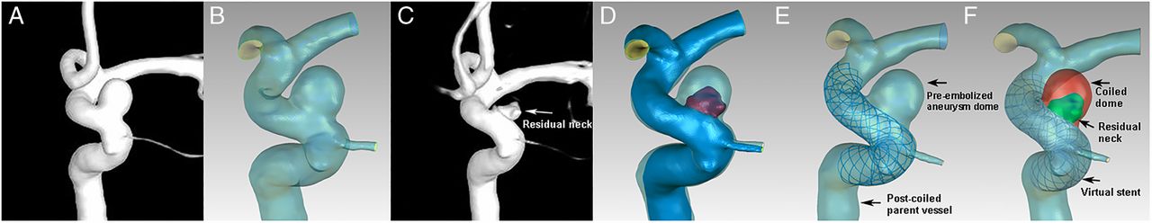
Illustrations of aneurysm model reconstruction. (A) The pre-embolized 3D aneurysm image. (B) The pre-embolized aneurysm reconstructed geometry. (C) The post-coiled 3D aneurysm image. (D) The match of pre-embolized and post-coiled aneurysm geometries (red region indicates the residual neck after coil embolization). (E) The stented aneurysm geometry fused by the pre-embolized aneurysm dome and the post-coiled parent vessel. The stent was virtually and specifically deployed in the parent vessel. (F) The post-coiled aneurysm model. The red region was filled with coils and modeled by the porous media method. The green region indicates residual neck and the stent was deployed in the parent vessel.
We used the porous media method for intra-aneurysm coil modeling in the aneurysm dome region.9–11 Briefly, the aneurysm dome was filled with porous medium corresponding to the coil mass, and the remaining vessel volume, including the residual neck and parent vessel, was filled with fluid to represent blood flow (figure 1F). The permeability (К) is a measure of the fluid conductivity through the porous medium.10 ,11 To approximate the permeability of a porous medium, we used a simplified expression based on the capillary theory of Kozeny, as we had done previously. In this approach, the porous medium is approximated as a layer of solid material with straight parallel tubes of fixed cross-section intersecting the sample. The permeability is calculated according to the formula К=φ3/cS2, where S is the specific surface area of coils, φ is the porosity of the medium, and c is the Kozeny coefficient and c=2 is taken. The drag factor, CD, can be determined by using standard CD versus Reynolds number diagrams and was estimated to be 2.2.9–11
We developed a new virtual stenting workflow12 to deploy the Enterprise stent. Briefly, the workflow consists of three steps: (1) preprocessing, which isolates the parent vessel and generates a simplex mesh structure to the maximum inscribed sphere diameter along the vessel center line using vessel-specific initialization; (2) simplex mesh expansion, when the simplex mesh undergoes radial expansion using mathematical forces, and the deployment is stopped when the deployed simplex mesh has good apposition with the parent-vessel wall; and (3) postprocessing, which maps the Enterprise stent pattern on the deployed simplex mesh and sweeps the wires into the 3D structures (figure 2).

The virtual stenting workflow of Enterprise stent deployment in the aneurysm geometry: preprocessing (A), simplex mesh expansion (B), and postprocessing (C).
Finally, the post-coiled aneurysm model was created using a porous media method and virtual stenting technique (figure 1F). In addition to comparing the hemodynamics between recanalized and stable groups based on the post-coiled aneurysm model, we created an aneurysm model with stenting alone for each case as control (figure 1E). In our clinical practice, the jailing technique was used in the present cases. First, a stent is deployed to jail the microcatheter, and coil embolization is then performed. Therefore, we created a group of such models as controls to estimate the hemodynamic effect of stenting and coiling by comparing flow alterations during the entire procedure among the three models.
CFD simulations and hemodynamic analysis
We performed the simulations described in our previous studies.4 ,13 To create finite-volume tetrahedral elements for CFD simulation, the deployed stent was merged with the aneurysm geometry using mesh-generation software (ICEM CFD, V.14.0; ANSYS Inc, Canonsburg, Pennsylvania, USA). The largest element was 0.2 mm, and the element size on the stent was set to 0.025 mm for adequate representation of the stent geometry, which was approximately one-third of the width of the strut of the Enterprise stent (0.078 mm). Mesh sizes ranged between 1.7 and 8.5 million elements for the untreated cases and from 7.1 to 13.9 million elements for the treated cases. ANSYS CFX V.14.0 (ANSYS Inc) was then used to solve the flow-governing Navier–Stokes equations, assuming laminar, incompressible, Newtonian blood flow. The density and dynamic viscosity of blood were specified as 1060 kg/m3 and 0.004 N s/m2, respectively. The blood vessel wall was assumed to be rigid, with no-slip boundary conditions. A pulsatile velocity profile obtained by transcranial Doppler in a normal subject was applied for the inflow boundary condition. The pressure distribution along the parent artery and in the aneurysm was then computed from the falls in pressure calculated during the CFD simulations with respect to the p=10 000 Pa value prescribed at the outlets.14 The flow waveforms were scaled to achieve a mean inlet wall shear stress (WSS) of 15 dyne/cm under pulsatile conditions.15 Three cardiac cycle simulations were performed for numerical stability and the last cardiac cycle was collected as output.
We then postprocessed and visualized the results of these simulations with the ANSYS CFD-Post. The hemodynamic results at peak systole were carefully examined at three regions: aneurysm neck plane, residual neck, and aneurysm dome (figure 1F). All results were collected before, during (after stent deployment), and after SACE. As described by Dhar et al,16 who obtained estimates on multiple views of aneurysm geometries, the IA neck plane was defined and created as the location from which the aneurysm sac pouched outward from the parent artery. Because the aneurysm models (pre-embolized, stented, and post-coiled model) maintained the same geometry coordinate, the aneurysm neck planes were at the same locations in the three models of each case. The area-averaged and maximum flow velocities at the aneurysm neck plane were calculated. At the residual neck and aneurysm dome, the average flow velocity, maximum velocity, and spatial-averaged WSS were calculated. Because the flow in aneurysms before and after embolization was different in each case, we used a reduction ratio, calculated as (parameterpre—parameterpost)/parameterpre, as a normalized parameter to allow comparison among patients.
Statistical analysis
For qualitative data, χ2 test or Fisher's exact test was used to compare the differences between the recanalized and stable groups. For quantitative data, the Mann–Whitney U test was used to compare two groups. Friedman's rank-sum test was used to analyze the hemodynamic effects of stents and coils by comparing the results among pre-embolized models, stented, and post-coiled models. A p value <0.05 was regarded as statistically significant. Statistical analysis was performed using IBM SPSS Statistics for Windows, V.21.0 (IBM Corp, Armonk, New York, USA).
Results
After application of screening criteria, 27 patients with 27 paraclinoid aneurysms were included and divided into two groups (seven in the recanalized group and 20 in the stable group) by angiographic result at follow-up. All cases in our study were unruptured and treated with a single Enterprise SACE.
Common risk factors
Patient demographics and morphology of recanalized and stable aneurysms are shown in table 1. Statistical analysis showed no significant difference in any factor between groups.
Patient demographics and aneurysm morphology in recanalized and stable aneurysms
Hemodynamic alterations by stent deployment
The hemodynamic results of 27 aneurysms are summarized in table 2 and online supplementary table S1.
Hemodynamics of 27 aneurysms in pre-embolized, stented, and post-coiled models
At the neck plane, the area-averaged flow velocity in 27 aneurysms was significantly reduced (reduction ratio, 11.9%; from 0.31±0.10 m/s to 0.27±0.09 m/s) (p<0.001) between before and after stent placement (see table 3 and online supplementary figure S1). Maximum velocity was also decreased, but the reduction was not statistically significant.
Multiple comparisons of area-averaged velocity at aneurysm neck plane among pre-embolized, stented, and post-coiled models
At the residual neck, all parameters except WSS were significantly decreased after stent deployment (table 2). Averaged velocity and maximum velocity decreased significantly (reduction ratios, 12.3%; from 0.23±0.12 to 0.20±0.11 m/s (p=0.003), and 12.2%; from 0.58±0.18 to 0.51±0.17 m/s (p<0.001), respectively). The WSS increased mildly but not significantly (reduction ratio, −4.8%; p=1.000).
At the aneurysm dome, all parameters were significantly decreased after stent deployment. Reduction ratios were 16.3% for average velocity (p=0.002); 16.5% for WSS (p=0.029); and 16.6% for maximum velocity (p=0.005) (figures 3 and 4; table 2).
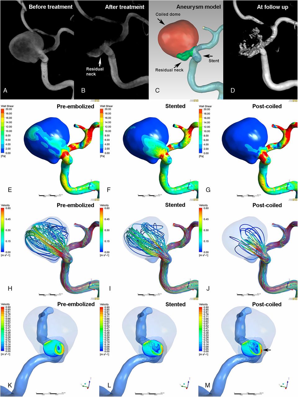
Illustrations of pre-embolized (E, H, and K), stented (F, I, and L), and post-coiled (G, J, and M) hemodynamics in a case that was recanalized at follow-up. The angiographic images before treatment (A), after treatment (B), at follow-up (D), and reconstructed aneurysm model (C) are depicted in the first row. Second row (E, F, and G): wall shear stress (WSS) distribution. Third row (H, I, and J): velocity streamlines. Fourth row (K, L, and M): velocity distribution on the neck plane. After stent placement, the WSS and flow velocity were decreased (F, I, and L). Further reductions were found after coil embolization (G, J, and M). At the end of procedure, although the overall flow velocity was decreased, the maximum blood flow at the aneurysm neck plane was concentrated and faster near the inflow area where the recanalization occurred at follow-up (M, black arrow).

Illustrations of pre-embolized (E, H, and K), stented (F, I, and L), and post-coiled (G, J, and M) hemodynamics in a case that was stable at follow-up. The angiographic images before treatment (A), after treatment (B), at follow-up (D), and reconstructed aneurysm model (C) are depicted in the first row. Second row (E, F, and G): wall shear stress (WSS) distribution. Third row (H, I, and J): velocity streamlines. Fourth row (K, L, and M): velocity distribution on the neck plane. After stent-assisted coiling, marked reductions in WSS and velocity were demonstrated (G, J, and M) and no high or concentrated velocity region at the neck plane (M, black arrow).
After stent deployment, reduction in flow velocity increased gradually from the neck plane to the aneurysm dome (11.9% at neck plane, 12.3% at residual neck, and 16.3% at aneurysm dome).
Hemodynamic alterations by coil embolization after stent placement
At the neck plane, further reduction in area-averaged velocity between after stent placement and after subsequent coil embolization was not significant (from 0.27±0.09 to 0.25±0.09 m/s, p=0.662) (see table 3 and online supplementary figure S1).
After stent placement, significant reductions were seen at the residual neck in averaged velocity (from 0.20±0.11 to 0.13±0.07 m/s, p=0.001) and WSS (from 5.32±3.16 to 4.22±2.24 Pa, p=0.008) after subsequent coil embolization. There was a tendency toward reduction in maximum velocity, but the difference was not significant.
After coil embolization, marked, significant decreases were seen at the aneurysm dome in averaged velocity (from 0.15±0.11 to 0.03±0.05 m/s, p=0.002), WSS (from 3.06±2.45 to 1.34±1.05 Pa, p<0.001), and maximum velocity (from 0.39±0.16 to 0.11±0.16 m/s, p=0.005) (figures 3 and 4; table 2).
Overall hemodynamic alterations by SACE
At the aneurysm neck plane, compared with results before treatment, the reduction ratio of area-averaged velocity was 17.2% after SACE and the reduction was significant (p<0.001, table 3). However, the alteration of maximum velocity did not show statistical significance.
Comparison of averaged velocity, WSS, and maximum velocity at the residual neck between before and after SACE demonstrated reduction ratios of 39.4% (p<0.001), 14.4% (p=0.019), and 22.9% (p<0.001), respectively.
Reductions in all parameters were also significant at the aneurysm dome. The reduction ratios of averaged velocity, WSS, and maximum velocity after SACE were 83.0% (p<0.001), 60.4% (p<0.001), and 77.4% (p<0.001), respectively. The reduction in averaged velocity was much higher at the dome region (83.0%) than at the neck plane (17.2%) and residual neck (39.4%), and much higher than after stent placement at the dome region (16.3%), which might promote intra-aneurysmal thrombosis.
Hemodynamic comparisons between recanalized and stable groups
Before treatment, none of the parameters at the three regions of interest differed significantly between recanalized and stable groups (see online supplementary table S2).
At the end of SACE, the inflow stream was markedly inhibited and redirected by the stent and coils (see figures 3 and 4, online supplementary figure S2). The mean reduction ratios of these parameters at the three regions were calculated and compared between groups (see table 4 and online supplementary figure S2). The only parameter that differed significantly between groups was the reduction in area-averaged velocity at the neck plane (p=0.016). At the aneurysm neck plane, the mean reduction ratio of area-averaged velocity in the recanalized group was 8.1%, which was significantly lower than that in the stable group (20.5%). The maximum velocity was increased by 2.1% in recanalized group and decreased by 5.4% in the stable group (p=0.240). At the residual neck, the reductions in all parameters were smaller in the recanalized group (see online supplementary figure S2). However, at the aneurysm dome, averaged velocity and WSS showed larger reductions in the recanalized group. These results indicated that the hemodynamic reductions at the neck plane and residual neck might be more important than those at the aneurysm dome in preventing recanalization.
Univariate analysis of reductions in hemodynamic parameters after stent-assisted coil embolization between recanalized and stable groups
Discussion
CFD simulations are widely used to study aneurysm initiation, growth, and rupture.13 ,17 ,18 However, less attention has been paid by CFD researchers to aneurysm recanalization after endovascular embolization. More importantly, studies of the application of an intracranial stent in the hemodynamic analysis of aneurysm recanalization following SACE are limited. In this study, we used an advanced virtual stenting technique and porous media modeling of coils to study a series of well-defined subgroup aneurysms to explore the role of hemodynamic effects in recanalization. Our data suggest that a significant reduction in flow velocity at the aneurysm neck plane may protect against aneurysm recanalization after SACE, and that aneurysm flow velocity can be substantially decreased with stent placement and coil embolization. However, the hemodynamics at the neck plane was less sensitive to coils.
Advanced techniques in CFD simulations of aneurysm outcome
The effect of hemodynamics on outcome of IAs after coil embolization alone has been reported previously.4 ,5 For aneurysms treated with SACE, intracranial stent modeling remains challenging in hemodynamic analysis of aneurysm outcome. Some studies6 ,19 performed the simulations by manually fitting the stent into the parent vessel, which might create a less accurate simulation. In another study,20 the stent was reconstructed by micro-CT in an animal model. That stent model was much more accurate but less likely to be used in such patients for specific stent reconstruction in studies of aneurysm outcome. In our research, patient-specific virtual stenting technology was used in the simulations, which might be a better option for CFD simulation of aneurysm outcome after SACE.
The coils also had a significant influence on intra-aneurysmal flow.21 ,22 In our previous studies,4 ,5 the embolized aneurysm dome was mimicked by a solid part filled with coils and without flow, based on post-coiled patient-specific aneurysm geometry. However, this method may not resemble the immediate post-procedural course before intra-aneurysmal thrombosis. The simulations with porous media for coil mass used in this present study may reflect the real situation more accurately, providing more valid results. Another study even excluded coils from the simulation because of technical difficulties.6 In our study, a porous media method was used in the post-coiled aneurysm model to simulate the coils. Nevertheless, simulation methods have several inherent limitations, which might be improved or resolved in the future. We used patient-specific information, such as packing density, aneurysm volume, and coils, to calculate the parameter settings in this study, which might improve the simulation accuracy.
Hemodynamics of aneurysm recanalization
Luo et al5 and Li et al4 studied hemodynamic effects on recanalization of aneurysms treated with coils alone and found that high WSS and flow velocity contributed to recanalization. However, no stent cases were included in those studies. Several reports have shown that the recanalization rate of aneurysms following SACE was lower than with coiling alone.2 ,23–25 It has also been reported that SACE can promote the occlusion of incompletely coiled aneurysms.2 With stent assistance, this situation is most likely owing to the hemodynamic effect on reducing flow impact. However, few CFD studies of aneurysm outcome following SACE have been published. In a study by Kono et al,6 16 vertebral artery aneurysms treated with an Enterprise stent and coils were evaluated. Although the goal of that study was to provide information that would reduce the rate of recanalization, there was recurrence in only one of the 16 cases, and it would be difficult to explain the mechanism of recanalization by flow reduction without controls. In our study, we compared the hemodynamics of seven recanalized aneurysms and 20 stable aneurysms and found that the reduction in flow velocity at the aneurysm neck plane was significantly higher in stable cases than in recanalized cases. Our results may provide helpful information for clinical practice.
Hemodynamic effects caused by stent and coils
Tremmel et al19 conducted a CFD study to quantify the effect of Enterprise stents on aneurysm hemodynamics. Their results confirmed that flow reduction is associated with the placement of the Enterprise stent, and that the effect could be increased by increasing the number of stents. Another CFD study on vertebral artery aneurysms showed that stent struts resulted in a velocity reduction ratio of 23.1%.6 The results of our study supported those findings, demonstrating that velocity was significantly decreased by stent placement and that the effect gradually increased from the neck plane (11.9%) to the aneurysm dome (16.3%). Therefore, the hemodynamic effect of stenting should be considered in CFD studies of aneurysm recanalization.
Some studies assessed the hemodynamic effect of coils in the aneurysm sac.21 ,22 However, in those studies, the relationship between the effect of coils and aneurysm outcome was unknown. Other CFD studies focused on aneurysm outcome but did not include coils in the simulation.6 In our study, after stent deployment, the averaged velocity at all aneurysm regions was further decreased by subsequent coil embolization, but such reduction was not significant at the neck plane. This may indicate that the coils had less hemodynamic effect at the aneurysm neck plane. The hemodynamics at the neck plane, where recanalization begins, was less sensitive to intra-aneurysm coils.
At the dome region, the reduction in velocity was as high as 80% after coil embolization in this study. Significant flow reduction by coils at the aneurysm dome may be central to the process of intra-aneurysmal thrombosis, and sufficient flow reduction at the aneurysm neck plane by stent placement might help to prevent recanalization. This may be one reason for the higher recanalization rate in aneurysms treated with coils alone than in aneurysms treated with SACE. Stenting could provide such flow alteration at the neck plane, and coils promote thrombosis at the aneurysm dome. It might also explain why aneurysms treated with a flow diverter and coils had a higher occlusion rate than those treated with a flow diverter alone.26
Mechanisms of aneurysm recanalization
High-flow conditions may significantly contribute to aneurysm recanalization via multiple mechanisms. Intra-aneurysm thrombosis after embolization could be hampered by high-speed flow and high WSS.27 ,28 Furthermore, high blood flow at the treated aneurysm neck may delay neointima formation over the stent surface and lead to coil compaction seen at follow-up.29 ,30 Therefore, flow reduction at the aneurysm neck plane by endovascular treatment may be a critical factor in preventing recanalization, which is consistent with our present results. In our study, the area-averaged velocity at the neck plane was decreased in the recanalized group after SACE, while the maximum velocity was increased in that group. These results suggest that high-speed flow was more concentrated and faster at the neck plane in recanalized cases after SACE, while the remaining area of the neck plane was occupied by lower-speed flow, and the overall flow velocity was decreased (figure 3). For large or complex aneurysms, a flow-diverter stent might be a better option because of its significant reduction of intra-aneurysmal hemodynamics.31 However, flow reduction is the key factor regardless of treatment, whether with a traditional or flow-diverter stent. A comparative study of the hemodynamic effects of a traditional stent and flow diverter, and associated clinical outcomes, is needed in the future.
Limitations
This study has some limitations. First, the small sample size might have influenced the results, and a study with a larger sample size should be conducted for validation. Second, several assumptions, such as rigid wall, laminar flow, Newtonian blood, and constant pressure at outlets, were used in our present aneurysm models for CFD simulations. Other factors, such as extraction of aneurysm neck place, number of mesh and prism layers, might also affect simulation results. We used the Kozeny coefficient of 2 to compute the permeability in porous media modeling and simplified the complex geometry of coil mass and the deployment of stent (angle changes of stent wires and elongation of stent). Such assumptions might affect the hemodynamic results. Third, our results might not be applicable to aneurysms at other locations, such as bifurcation aneurysms.
Conclusion
Aneurysm flow velocity can be significantly decreased by stent placement and coil embolization. However, the hemodynamics at the aneurysm neck plane was less sensitive to coils. Significant reduction in flow velocity at the aneurysm neck plane may be an important factor in preventing recanalization of paraclinoid aneurysms after stent-assisted subtotal coil embolization.
References
Supplementary materials
Supplementary Data
This web only file has been produced by the BMJ Publishing Group from an electronic file supplied by the author(s) and has not been edited for content.
- Data supplement 1 - Online figures
- Data supplement 2 - Online tables
Footnotes
Contributors JL contributed to the preparation of the manuscript and data collection. LJ and CW contributed to revision of the manuscript. SW, NP, JX, and YZ contributed to data analysis and interpretation. HM, AHS and XY contributed to the experimental design and manuscript revision.
Funding This work was supported by National Natural Science Foundation of China (grant Nos 81301003, 81171079, 81371315, 81471167, and 81220108007), Special Research Project for Capital Health Development (grant No. 2014-1-1071) and National Institutes of Health (R01 NS091075).
Competing interests None declared.
Ethics approval This study was approved by the ethics committee of Beijing Tiantan Hospital.
Provenance and peer review Not commissioned; externally peer reviewed.
Data sharing statement The authors agree to share any data on request. Any data from this study are available by contacting the corresponding author.