Article Text

Abstract
Objectives To integrate morphological, haemodynamic and mechanical analysis of carotid atheroma driving plaque disruption.
Materials and methods First, we analysed the phenotypes of carotid endarterectomy specimens in a photographic dataset A, and matched them with the likelihood of preoperative stroke. Second, laser angioscopy was used to further define the phenotypes in intact specimens (dataset B) and benchmark with histology. Third, representative vascular geometries for each structural phenotype were analysed with Computational Fluid Dynamics (CFD), and the mechanical strength of the complicated atheroma to resist penetrating forces was quantified (n=14).
Results In dataset A (n=345), ulceration (fibrous cap disruption) was observed in 82% of all plaques, intraplaque haemorrhage in 68% (93% subjacent to an ulcer) and false luminal formation in 48%. At least one of these ‘rupture’ phenotypes was found in 97% of symptomatic patients (n=69) compared with 61% in asymptomatic patients. In dataset B (n=30), laser angioscopy redemonstrated the structural phenotypes with near-perfect agreement with histology. In CFD, haemodynamic stress showed a large pulse magnitude, highest upstream to the point of maximal stenosis and on ulceration the inflow stream excavates the necrotic core cranially and then recirculates into the true lumen. Based on mechanical testing (n=14), the necrotic core is mechanically weak and penetrated by the blood on fibrous cap disruption.
Conclusions Fibrous cap ulceration, plaque haemorrhage and excavation are sequential phenotypes of plaque disruption resulting from the chiselling effect of haemodynamic forces over unmatched mechanical tissue strength. This chain of events may result in thromboembolic events independently of the degree of stenosis.
- Plaque
- Carotid Stenosis
- Endoscopy
- Cerebrovascular Disorders
- Hemorrhage
Data availability statement
All data relevant to the study are included in the article or uploaded as supplementary information.
This is an open access article distributed in accordance with the Creative Commons Attribution Non Commercial (CC BY-NC 4.0) license, which permits others to distribute, remix, adapt, build upon this work non-commercially, and license their derivative works on different terms, provided the original work is properly cited, appropriate credit is given, any changes made indicated, and the use is non-commercial. See: http://creativecommons.org/licenses/by-nc/4.0/.
Statistics from Altmetric.com
WHAT IS ALREADY KNOWN ON THIS TOPIC
It is currently broadly accepted that the majority of cerebrovascular events from carotid disease are not related to flow-limiting stenosis from plaque growth but rather from acute embolic events driven by plaque rupture and thrombosis at the arterial surface.
WHAT THIS STUDY ADDS
This study integrates morphological, haemodynamic and mechanical analysis of carotid atheromas and shows that fibrous cap ulceration, plaque hemorrhage and excavation are sequential phenotypes of plaque disruption resulting from the chiseling effect of haemodynamic forces over unmatched mechanical tissue strength. These phenotypes can be readily identified by a novel laser angioscope.
HOW THIS STUDY MIGHT AFFECT RESEARCH, PRACTICE AND/OR POLICY
This study provides a mechanistic framework of plaque disruption and healing independent to the degree of luminal stenosis and with well-defined phenotypes at the lumen/wall interface suitable for medical imaging.
Introduction
The management of patients with carotid atherosclerosis has overwhelmingly relied on the degree of stenosis as the main surrogate for carotid-related stroke aetiology, risk stratification and indication for intervention. Accumulating evidence suggests that structural and biological factors at the lumen/wall interface might be more significant than the degree of narrowing in determining the risk profile and root cause of a cardiovascular event.1 It is currently broadly accepted that the majority of cerebrovascular events from carotid disease are not related to flow-limiting stenosis from plaque growth but rather from acute embolic events driven by plaque rupture and thrombosis at the arterial surface.2 However, the management of carotid atherosclerosis has been mostly stagnant for the last three decades due to an overemphasised focus on the degree of carotid stenosis and the lack of a mechanistic framework of plaque disruption and healing with well-defined phenotypes at the lumen/wall interface suitable for medical imaging.
Plaque rupture, ulceration and plaque haemorrhage are known to be associated with atherosclerosis vulnerability, but no unifying theory has linked these phenotypes in a mechanistic paradigm of carotid plaque degradation. In this study, we integrate morphological, haemodynamic and mechanical analysis of carotid atheromas to unravel the complex biomechanical process of carotid plaque disruption and thromboembolism.
Materials and methods
Structural analysis of carotid atheromas with dataset A
Dataset A
Following approved institutional protocol and signed informed consent, a total of 413 atherosclerotic plaques were obtained at carotid endarterectomy (CEA) surgery in patients with radiologically identified≥70% stenosis of carotid artery. Patients were selected for CEA either due to asymptomatic progression of stenosis or due to presentation with a symptomatic cerebrovascular event (stroke, transitory ischaemic attack and retinal ischemia) attributed to carotid stenosis. Procedures were performed by the senior author during a 20-year period 1985–2005. All plaques were removed en bloc without violation of the lumen or disruption of the atheroma (figure 1A–D). Plaques that sustained mechanical damage during removal were discarded. The endovascular surfaces of each specimen were imaged at ×25 magnification followed by longitudinal and/or transversal sectioning to optimally visualise the structural pattern of plaque degradation at the interface between the lumen and the arterial wall (figure 1E–G). The set of photographs, macroscopic grossing reports and clinical data formed dataset A.
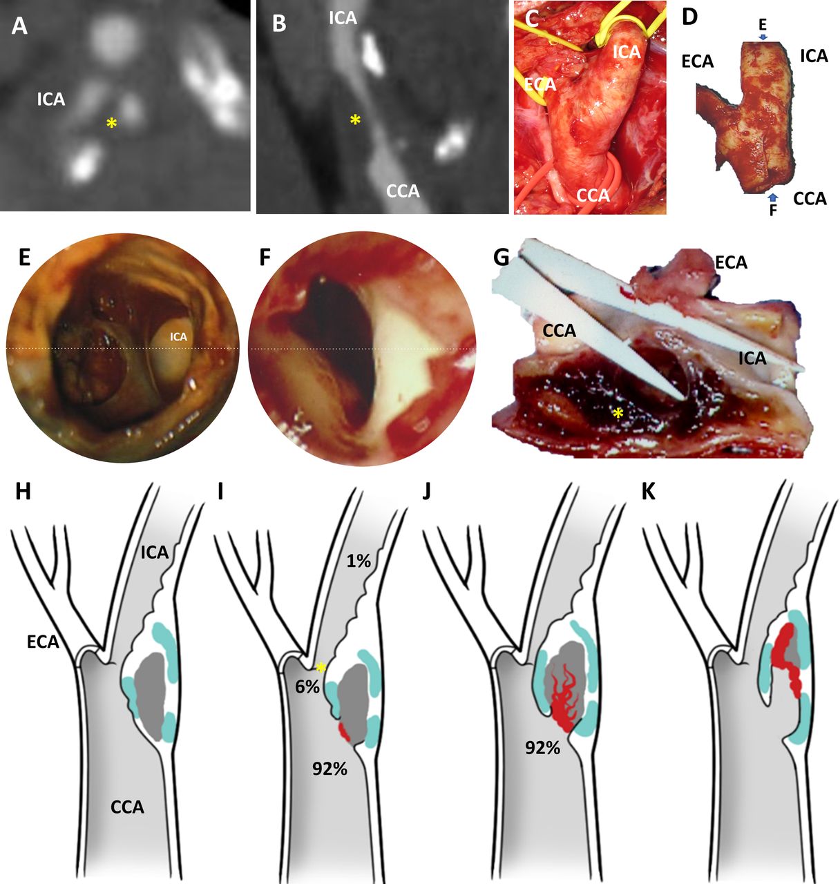
Phenotypes of carotid endarterectomy specimens. Preoperative computational tomographic angiography in axial (A) and sagittal reconstructions (B) reveal mixed density atheroma (yellow asterisk) leading to >70% stenosis in the common carotid artery (CCA) and proximal internal carotid artery (ICA). At surgery, the CCA, external and carotid arteries (ECA and ICA) are exposed and atheromas removed en bloc without luminal violation and minimising disruption (D). The lumen/wall interface of each specimens were imaged with an operative microscope (×25 magnification) from the flow inlet (E) and outlet (F) perspective. Based on the findings and the preoperative images, plaques were dissected both longitudinally (G) and/or transversally to optimally visualise the interface between the lumen and the atheroma (yellow asterisk). In the cohort, four recurrent phenotypes were identified: (H) Atheroma with no discontinuity of the fibrous cap; (I) atheroma with ulcer (ie, loss of continuity of the fibrous cap, generally round shaped or oval) upstream (92%), at (6%) or downstream (1%) to the point of maximal stenosis (asterisk); (J) atheroma with an intraparenchymal haemorrhage, in continuity with an ulceration in 92% of cases; (K) atheroma with false luminal formation (excavation within the plaque). Atheroma subcomponent in (H)–(K) are color coded: white for fibrous cap, light blue for calcified tissue, grey for necrotic core and red for thrombus.
Structural analysis
Plaque morphology characterisation was conducted using dataset A by independent reviewer HM, blind to patients’ clinical data. Macroscopic structural findings were described and categorised in nominal variables. The pathological phenotypes employed in our data collection and analysis consisted in unruptured cap (no discontinuity exposing the necrotic core or associated haematoma), ulceration (loss of continuity of the fibrous cap), intraplaque haemorrhage (IPH, identified as the presence of a formed blood clot within the plaque) and false luminal formation (FLF, excavation within the plaque lumen forming a channel, usually parallel to the true lumen that does not communicate with the true lumen over a portion of its length). As two or more phenotypes can coexist in the same specimen, a given plaque could be placed in multiple categories; but for statistical purposes, the final classification was based on the highest risk feature. The location of the disruption at the arterial surface was classified as (1) upstream to the point of maximal stenosis (POMS), that is, proximal or at the ‘shoulder’ of the cap; (2) at the POMS; and (3) and downstream to the POMS. Structural findings were further analysed on the presence of IPH exposed to the blood stream, relationship of the IPH to the downstream ending of a plaque (not reaching, reaching, extruding through the plaque ending into the lumen) and presence of necrotic core exposed to the blood stream. FLF was subclassified as blind ended (close-end) or fenestrated (when false lumen opens back to the true lumen cranially). Based on macroscopic appearance of the luminal/wall interface both by surface anatomy and cross-sectional images, IPH was subdivided into ‘contained’ IPH, when the thrombus fully confined within the atheroma by an intact fibrous cap, and ‘contiguous’ IPH, when the thrombus in the atheroma was at least partially exposed to the intraluminal environment.
Clinical correlation
Overall, 107 cases in dataset A with high-quality images for morphological classification also specified the presence or absence of cerebrovascular event (69 symptomatic and 38 asymptomatic). These 107 cases were divided into 4 groups: group A: plaques with no ulceration; group B: plaques with only ulceration; group C: plaques with ulceration and IPH; and group D: plaques with all three stages of excavation.
High-definition structural analysis of the lumen/wall interface by laser angioscopy with dataset B
Following institutional approval and informed consent, 30 CEAs from patients with symptomatic carotid disease and >50% stenosis were collected by the first authors between 2020 and 2021 using the en bloc technique. Specimens were obtained from a population aged 69 years in average (SD 13), formed by 70% of men. All specimens in this dataset B were imaged within 24-hour harvesting with a polychromatic 1.2 mm scanning fiber endoscope (SFE) angioscope (console from VerAvanti; scope from the University of Washington Human Photonics Lab). Briefly, angioscopic videos and still images were obtained as previously described and plaque phenotypes were classified as above (LS).3 Then, specimens were fixed in 10% neutral buffered formalin for 12 hours at 4°C, decalcified if needed in buffered ethylenediaminetetraacetic acid for 3–5 days and embedded in paraffin. Sections were obtained (5 µm and 10 µm thick) every 1 mm and stained with H&E for assessment of overall arterial and plaque histology. Histology slides were independently evaluated by a pathologist (DG) unaware of the patient’s medical history and the ex vivo angioscopic findings, and lesions were categorised according to the modified American Heart Association (AHA) histopathological classification.4
Computational fluid dynamics of the structural phenotypes of carotid artery disease
Following institutional approval, representative vascular geometries of each phenotype were reconstructed from preoperative computed tomography angiography (CTA) of selected dataset B cases and shear stress (force per unit area directed parallel to the wall), dynamic pressure (force per unit area directed into the wall as a result of the motion of the fluid) and flow pathlines (trajectories that individual fluid particles follow over a certain period) were obtained. CFD model including geometry and meshing, materials, boundary conditions and solver can be found in the online supplemental material.
Supplemental material
Mechanical analysis of thromboatheroma
Needle insertion test was conducted to compare mechanical strength of the different histological components of advanced and complicated carotid plaques to resist penetrating forces (five disrupted thromboatheromas and two cadaveric fibroatheromas).5 A 1 mm diameter stainless steel needle with a 30° bevel angle trocar tip (symmetric three-plane stylet) was mounted to and axially translated at 0.05 mm/s by a computer-controlled motorised linear stage (200cri; Siskiyou, Grants Pass, Oregon). The needle shank was covered by blue tissue marking dye to indicate cutting path on plaque specimens for histology analysis. The specimen was fixed in a 3D printed holder, exposing the region of interest via a hole for needle insertion and mounted to a force sensor (Gamma; ATI Industrial Automation, Apex, North Carolina, USA). The position of the needle and force data were recorded at a frequency of at 50 Hz, with an averaging window of 10 for the force data, and the advancement was done at 0.05 mm/s.
All specimens were then sectioned, and macroscopic photos of the atheroma revealing the needle path though the full thickness were obtained with Canon PowerShot G16 Digital Camera. Then, tissue sections were processed, and histological images obtained as described previously. Needle insertion data derived from 14 full-thickness insertion points were then matched to the type of atherosclerotic tissue, location within the plaque and surrounding elements based on the needle travel path. The mean and SD of the penetration forces for the different atherosclerotic components were analysed.
Statistical analysis
χ2 test was performed for the comparisons of proportions and ratios. Weighted Kappa statistics were calculated to test agreement between angioscopic and pathology diagnosis using conventional histological techniques. Kappa statistics ranged from 0 (no agreement) to 1 (complete agreement). Statistical significance was indicated p<0.05. Analysis were conducted using the SPSS (V.25) software.
Results
Phenotypes of plaque disruption and preoperative symptoms
A total of 345 cases were available for analysis in dataset A (figure 1A–G and table 1). In this cohort, there were 62 atheromas (18%) with an intact fibrous cap (figure 1H) and 283 atheromas (82%) with an ulceration defined as a macroscopic circular or oval discontinuity of the fibrous cap (figure 1I). IPH was identified in 233 plaques (68%), in which ulceration was present in 231 specimens (99%). Of these specimens, there were 215 plaques (92%) where IPH was in continuity with ulceration (figure 1J). Intraplaque FLF (figure 1K) was identified in 165 specimens (48%) and often extended deep into the plaque and distal to the site of fibrous cap rupture, but were generally confined to the plaque and did not extend into the media or adventitia. There was an increased rate of ulceration compared with rate of IPH, considering ulceration as an independent group (p<0.0001, 95% CI 7.3 to 20.5) or ulceration occurring proximal to POMS (p=0.01, 95% CI 1.1 to 14.8). There was also an increased rate of IPH when compared with FLF (p<0.0001, 95% CI 12.4 to 27.2).
Structural analysis of a cohort of carotid endarterectomy specimens
As showed in table 2, 97% of the CEA specimens obtained from symptomatic patients had a rupture phenotype, while there were only 61% in the asymptomatic population. Progression of excavation was directly associated with increased chance of having manifested a cerebrovascular event, suggesting that plaque disruption is a process that starts with fibrous ulceration upstream to the POMS leading to IPH and progressive excavation.
Correlative analysis of plaques phenotypes with preoperative symptoms
Morphological analysis of plaque phenotypes contextualised to individualised haemodynamic conditions
The analysis of the lumen/wall interface of a cohort of intact CEA specimens (dataset B) causing>50% stenosis with high-resolution laser angioscopy demonstrated: (1) plaque ulcerations: (figure 2A) full-thickness discontinuity of the fibrous cap of the atheroma and almost universally identified proximal to the POMS (online supplemental video 1) at regions of local high wall shear stress (WSS) with peak value of 171 Pa (online supplemental video 2), over 60 times higher than that in healthy human carotid6; and high dynamic pressure with a peak value of 28 kPa or 210 mm Hg (online supplemental video 3), two times as the mean carotid pressure; (2) blind-ended FLF: (figure 2B) excavations into the necrotic core from an ulcerative region and generally associated with haematomas (online supplemental video 4 demonstrates angioscopic visualisation of two excavations in the shoulder of the plaque), with local high WSS (online supplemental video 5) and dynamic pressure (online supplemental video 6) preferentially at the opening into the main lumen and directed toward the cranial side of the excavation. Shallow excavations are associate with high dynamic pressure (figure 2B5 and online supplemental video 6) and a vigorous stream vortex (figure 2B6 and online supplemental video 7). Deep excavations have a tapering dynamic pressure toward the apex of the crater (arrowhead in figure 2B7 and online supplemental video 8) with slow and disorganised flow (figure 2B8 and online supplemental video 9); (3) fenestrated FLF: deep excavations expanding cranially with multiple openings between the false and the true lumen (online supplemental video 10 and figure 2C) with regions of high dynamic pressure (online supplemental video 11) and WSS (online supplemental video 12) impacting the remaining fibrous cap; (4) plaque haematoma: thrombosis at the lumen/wall interface was the main driver for luminal narrowing (online supplemental video 13 and figure 2D) and associated with a local region of high dynamic pressure (online supplemental video 14), and WSS (online supplemental video 15) at the POMS. The high dynamic pressure and shear stress propagated along to the arterial wall confronting the rapid jet of blood crossing the POMS and were opposite to a column of stagnated blood with minimal haemodynamic stress and flow. We found near-perfect agreement (kappa=0.99; 95% CI 0.96 to 1.000, with kappa of 0, no agreement; kappa of 1, complete agreement) with weighted Kappa statistics between angioscopy and pathologic diagnosis by conventional histological techniques to identify phenotypes of type 4 plaques. By angioscopy, fibrous cap rupture (ulceration) was seen in 27 specimens, haemorrhagic plaques in 22, and FLF (excavation) in 12. The single error found in 30 assessments was the identification of an IPH by histology, which was not recognised in angioscopy given the small haematoma size and deep location remote from the lumen.
Supplementary video
Supplementary video
Supplementary video
Supplementary video
Supplementary video
Supplementary video
Supplementary video
Supplementary video
Supplementary video
Supplementary video
Supplementary video
Supplementary video
Supplementary video
Supplementary video
Supplementary video

Morphological analysis of plaque phenotypes contextualised to individualised haemodynamic conditions. Plaque ulcerations (A1) were identified as full thickness discontinuity of the fibrous cap of the atheroma per angioscopy (A2) and remained occult to CTA (arrowhead in (A3) points the approximate location of the ulcer identified per angioscopy in (A2)). CFD simulations revealed a region of local high dynamic pressure directed into the plaque in the same region of the ulcer ((A4) and arrowhead in insert). Blind-ended false luminal formation (FLF) (B1) was identified by SFE angioscopy as a crater excavating the atheroma from an ulcerative region generally associated with haematomas (arrowhead in (B2)). These excavations in the atheroma corresponded to deep surface irregularities in CTA (arrowhead in (B3)). CFD simulation in FLF demonstrated a region of local high dynamic pressure directed cranially ((B4) and arrowhead in insert). In shallow excavations, the jet of blood chisels the plaque core with high dynamic pressure (B5) and following a vigorous stream vortex (B6). In deeper excavations, the dynamic pressure of the blood significantly tapers off toward the apex of the crater (arrowhead in (B7)) and the jet of blood becomes slow and disorganised with stagnation towards the apex of the excavation (B8). Fenestrated FLF (C1) was identified per angioscopy as deep and broad excavations, usually parallel to the true lumen, with one or more opening communicating the false with the true lumen (arrowheads in (C2)). False lumens running through atheroma were also identified in CTA (inlet and outlet with arrowheads, point of maximal stenosis with asterisk in (C3)). In these cases, CFD simulation revealed localised regions of high dynamic pressure within the plaque’s FLF with maximal stress over the remaining fibrous cap from both the luminal and pseudoluminal surfaces (yellow and black arrowheads, respectively, in (C4)). Plaque haematomas (D1) were generally exposed at the lumen/wall interface and their geographic distribution and thrombus type readily identified by angioscopy (D2). Plaque haematomas frequently had an intraluminal extension with cranial propagation into the internal carotid artery (ICA) (arrowhead in a CTA in (D3)). In cases of critical stenosis, CFD simulation revealed a region of high dynamic pressure at the POMS with propagation to one side of the arterial wall circumference and minimal haemodynamic stress in the opposite side (arrowheads point high stress at the POMS and downstream in (D4)). As the flow passes through the narrowed luminal corridor, it is directed towards one side of the arterial lumen leaving the opposite side in relative stagnation, which favours clot formation (arrowheads in (D5)). Atheroma subcomponent in (A1–D1) are color coded: white for fibrous cap, light blue for calcified tissue, grey for necrotic core and red for thrombus. Refer to the online supplemental videos for the dynamic colour bars of the contour map of the CFD. ECA, external carotid artery.
Behavior and strength of carotid arterial wall and atheroma constituents to penetrating forces
The cutting force of individual atherosclerotic component was analysed based on the needle insertion force curve of the whole specimen (figure 3 and table 3). Based on the peak needle penetration forces, the necrotic material (0.39 N±0.23) and thrombus (0.42 N±0.23) are the weakest followed by the fibrous cap (0.6 N±0.36), fibrotic intima (1.05 N±0.43) and the tunica media (1.35 N±0.82). Densely calcified tissue is the strongest component (5.52 N±3.51) and requires the highest cutting forces to be penetrated. The analysis revealed that the slope of the penetration curve depends on the stiffness of the tissue (slow slope in elastic tissues, steep slope in hard tissues).
Cutting force of individual atherosclerotic component from the needle insertion test

Mechanical testing of atherosclerotic components of carotid plaques: needle penetration tests of atheroma was conducted in a custom-made platform (blue dots in (A) corresponds to insertion points in atheroma). The position of the needle and force data were recorded at a frequency of at 50 Hz and then datasets correlated with the corresponding atheroma cross section (dotted rectangle in (A) and cross section in (B)). Tissue correlation was refined by histological analysis of the atheroma section (note: blue trajectory of needle in (B) and corresponding histological cut in (C)). The number of cutting force datapoints, the mean cutting force and SD among the datapoints for each arterial and atherosclerotic component were calculated (D). The tissues analysed in the cohort (E–F) were: fibrous cap (FC), necrotic core (NC), thrombus (T), fibrotic intima (FI), calcification speckled (CS), calcification dense (CD) and tunica media (TM). Cutting force curves with histological correlation of representative advanced and complicated carotid atherosclerosis (complex atherothrombotic lesion in (G) and partially calcified in (H), thromboatheroma in (I) and calcified fibroatheroma in (J)) are presented (dotted yellow arrow in (C) and (G–J) indicates pathway of the needle).
Discussion
This study introduces a unifying theory of plaque disruption that includes the continuum of pathological phenotypes throughout advanced stages of carotid artery disease and the interplay of haemodynamic forces and tissue biomechanics driving these complex structural changes.
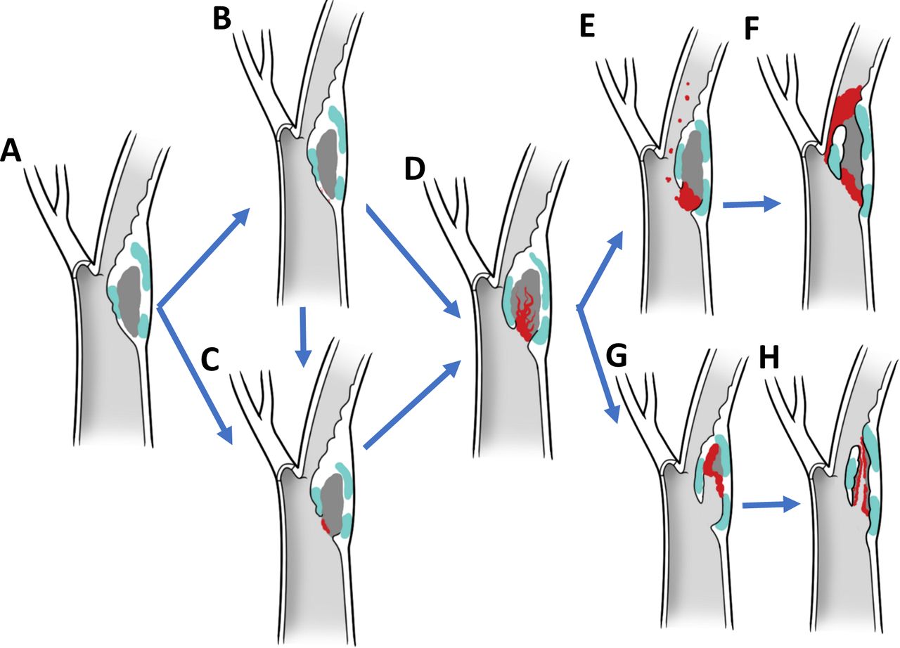
Imaging and histopathologic studies have demonstrated that plaques associated with symptoms, independently from the degree of stenosis, are more likely to have thrombus, ulcer, low fibrous content and large necrotic core, heavy macrophage infiltration, and high microvessel density.7–9 These studies of plaque ruptures have allowed us to define morphological criteria that are statistically associated with symptoms and, therefore, have led us to consider that they characterise plaques at high risk for rupture.10 Although valuable, these pathological findings are not embedded within a mechanistic framework and a chain of events that finally lead to a thromboembolic event. Histological phenotypes have proven to be insufficient in predicting which atheroma will undergo plaque progression on a per-patient basis.11 Based on our results, plaque disruption and thromboemboli are haemodynamically driven processes unleashed by unmatched excavatory forces at the lumen/wall interface. The disruption of a weakened fibrous cap (figure 4A–C) exposes the necrotic material to the chiselling effect of the blood stream and allows inflow of blood from the arterial lumen resulting in a plaque haematoma (figure 4D). We conjecture that this triggers a complex and dynamic process characterised by the interplay of pro-occlusive and proexcavatory conditions. Pro-occlusive conditions include thrombus formation in the arterial lumen or within the atheroma with forceful entry of blood and acute plaque expansion resulting in stenosis and/or complete occlusion (figure 4E–F). Proexcavatory conditions include fibrinolysis and fragmentation of fibrous cap, necrotic core and/or thrombus with downstream material migration and false lumen formation (figure 4G–H). The chiselling and downstream showering of plaque content is supported by the well-known Hollenhorst plaques (bright, refractile lesions in the retina related to cholesterol crystal embolisation) and histological analysis of emboli retrieved in large vessel occlusion stroke revealing plaque content.12 This excavatory phenomenon, which is originally vigorous as peak haemodynamic stress impacts a shallow ulcer, eventually is mitigated by elongation of the false lumen and possibly overwhelmed by in crescendo thrombogenicity due to flow stagnation and larger contact with the necrotic material, resulting in plaque thrombosis. This phenomenon tends to halt the excavatory process, at least temporarily, as it is likely that in the lifetime of a plaque there are cycles of progression/stabilisation. This is supported by accumulated fibrous tissue from organised thrombi at healed repair sites and the increased risk of future stroke or transient ischaemic attack in patients with haemorrhagic carotid atherosclerotic disease.13 During the early stages of a ‘hot’ plaque, cycles of excavation and thrombosis may occur more frequently and with larger thromboembolic potential, explaining the higher risk of a recurrent cerebrovascular event in the first few weeks after the initial insult.14 In addition, as demonstrated in our data, although the early phenotypes are the most commonly identified at the lumen/wall interfaces of plaque causing>70% stenosis, the likelihood of having a cerebrovascular event was higher with more advanced phenotypes in our paradigm, which is independent to stenosis.15
Biomechanical paradigm of plaque disruption with phenotypic hallmarks and driving forces. In this paradigm, plaque disruption starts on a thin-walled atheroma (A) with a fissure (B) or ulceration of the fibrous cap (C), followed by excavation of the necrotic core with formation of a plaque haematoma (D). If pro-occlusive conditions prevail, thrombosis progresses leading to luminal extension of the thrombus, narrowing and occlusion (E,F). If proexcavatory conditions prevail, the necrotic core is progressively excavated and plaque content embolised downstream mixed with thrombi resulting in blind-ended or double-ended false luminal formations (G,H).
In this biomechanical hypothesis of plaque disruption, the rupture of the fibrous cap is due to unmatched cyclical haemodynamic forces inducing mechanical fatigue. The role of fatigue in arterial degeneration, particularly the elastin fragmentation and disruption,16 has been widely recognised considering the pulsed blood flow. Fatigue failure has also been considered as a potential cause of atherosclerotic plaque fissuring.17 Under cyclic loading, the microcracks inside the tissue grows and the growing speed increases with the magnitude of pulses.18 In the cases of blood flow surrounding the plaque, the magnitude of pulses is evaluated by the dynamic pressure. We found that the peak dynamic pressure is 19.6 times higher than that of the average dynamic pressure (online supplemental material) indicating a large pulse magnitude. Based on the fatigue theory, a higher magnitude of cyclic loading would fail the material faster.19 This corresponds to the collocation we identified between the area of elevated hydrodynamic forces in our CFD results and the region of ulcer. Therefore, even though the absolute values of blood pressure and shear (in the order of 1 kPa from the CFD modelling) are smaller than the fibrous cap strength (10–100 kPa),20 21 the pulsating hydrodynamic forces in vulnerable regions can cause fatigue failure of the material and lead to ulcers and ruptures. In addition, our analysis demonstrated that if the layer behind a given tissue is weaker, then the force to induce the same strain/displacement for breaking the tissue would be smaller. Therefore, the presence of a soft necrotic core in a juxtaluminal position would decrease the mechanical strength of the overlaying fibrous cap, increasing the likelihood of fibrous cap rupture. This geographic-specific mechanical behaviour may explain the high propensity to rupture and result in thromboembolic complications of thin-cap fibroatheromas as described in the previous histopathological studies.22
In our theory, fibrous cap fracture allow the chiselling forces of the blood stream to excavate the necrotic core and form an IPH.23 This mechanism is supported by the mechanical testing here presented that show the necrotic core to be significantly easier to excavate by penetrating forces compared with the fibrous cap (0.39N vs 0.6N, respectively). Based on this, if a fibrous cap ruptures, blood will penetrate the necrotic core resulting in excavation, embolisation (of necrotic core and/or clot) and thrombosis. In support of this chain of events, Daemen et al reported that fissures were present in 58% of a cohort of 244 CEA specimens,24 and in 92% of cases the fissures were connected to a haemorrhage dissecting the tissue planes of the fibrous cap and/or a tract extending into the necrotic core. These fissures were located proximal to the POMS in 88% of cases and histologically were characterised by a tear in the fibrous cap lifting a layer of the intima from the underlying fibrous tissue. Our observations corroborate this hypothesis and provide mechanistic evidence of this phenomenon. In our cohort, 92% of plaques ruptures occurred upstream to the POMS, which colocalises with the region of highest haemodynamic stress and known to have the most intense inflammatory status and thinner fibrous caps.25 26 In addition, IPH was near universally associated with the presence of an ulcer, which was contiguous with the IPH in 92% of cases.
As supported by our observations and experiments, IPH and thromboemboli are direct consequence of surface disruption and may explain the occurrence of embolic strokes independently to the degree of stenosis. This is likely the predominant mechanism of IPH in symptomatic and vulnerable plaques rather than the dominant view supporting erythrocyte extravasation from fragile microvessels into the plaque.27 28 In addition to lack of biomechanical evidence, the latter origin of IPH in symptomatic plaques has been also questioned by other groups that have found a strong association of fibrous cap fissures in the proximity of IPH but not of plaque microvasculature.24 29 30
Considering that IPH detection by MR is rapidly emerging as an important radiographic marker for stroke aetiology and risk stratification, especially in the setting of mild stenosis, the accurate diagnosis of the pathophysiological origin of IPH may be of relevance.31 We think that IPH due to fibrous cap disruption would be a more accurate imaging biomarker to diagnose carotid-related strokes and have a higher likelihood of future cerebrovascular event. More research needs to be conducted to evaluate wheatear MR or other technologies can distinguish between IPH resulting from surface disruption versus vasa vasorum leakage and understand the natural history of each conditions.32
The proposed biomechanical paradigm of plaque disruption, along with phenotypes suitable for medical imaging, could improve our capacity to detect carotid-related stroke aetiology and appropriately select patients for revascularisation beyond the degree of stenosis. Although stenosis from thrombus formation may indicate an advanced disrupted plaque in a prothrombotic phenotype, it may not confer any protective benefits if used to indicate a surgical resection of a mechanically stable fibroatheroma. In addition, stenosis can actually be misleading if used as a surrogate for stroke aetiology in a proexcavatory situation. Our proposed framework supports the hypothesis that a significant proportion of patients diagnosed with ‘embolic strokes of unknown source’ may actually suffer from thromboembolic phenomena from undiagnosed ulcers, fissures, excavations, IPH or erosions in non-stenotic (<50% narrowing) carotids. These patients could be classified as having a ‘symptomatic non-stenotic carotid’,33 and benefit from targeted interventions such as CEA.34
There are some limitations in this study to consider. First, the paradigm mostly derives from CEA specimens causing>50% stenosis. As such, it is conceivable that phenotypes occurring in carotid disease with mild or no stenosis are not fully captured. Although our results could explain stroke in non-stenotic carotids, more research is needed to unravel the mechanism by which non-stenotic plaque may result in a thromboembolic event. Second, the work here presented is mostly descriptive and mechanistic in nature and future clinical research should be conducted to analyse the impact of other clinical variables such as age, sex, race, comorbidities in the proposed mechanism of plaque disruption. Third, the theory here introduced needs to be further validated with fluid/tissue interaction models and comprehensive biomechanical characterisation of complex thromboatheromas. Fourth, most of the structural analysis here presented derives from high-definition images obtained with a surgical microscope and a laser angioscope rather than histology, which is classically considered the gold standard to evaluate an atheroma. Despite this apparent limitation, we found a high correlation between grossing/angioscopy and histology, and the interpretation of the structural phenotypes at the lumen/wall interface was significantly enhanced by analysing the whole specimens. To this end, we only analysed intact specimens removed en bloc and without any mechanical manipulation at the endovascular surface. After imaging the whole endovascular surface with microscopes and angioscopes, the tissues were strategically sectioned longitudinally to intersect ulcerations, excavation and IPH and better inspect the arterial lumen/wall interface. We think that the critical structural information observed with these manoeuvres would have been exceedingly difficult to interpret on histology. Histology of atheroma is usually done with cross section (as the tissue is too large for longitudinal processing), it creates artefacts (ie, fixation, decalcification, dehydration, embedding, cutting and staining), and only provides data from a small region of the plaque (typically, 5 µm thick cross-sectional slices of tissues are imaged every 1 mm of plaque, resulting in 99.5% of the plaque not being analysed).
Conclusions
Fibrous cap ulceration, plaque haemorrhage and excavation are likely sequential phenotypes of plaque disruption resulting from the chiselling effect of the haemodynamic forces. This chain of events may result in thromboembolic events independently to the degree of stenosis. This conceptual mechanistic framework for carotid artery disease along with defined phenotypical hallmarks and novel imaging technologies has the potential to improve our ability to diagnose carotid-related strokes, better stratify risk of vulnerable plaques, indicate intervention and develop new treatment strategies.
Data availability statement
All data relevant to the study are included in the article or uploaded as supplementary information.
Ethics statements
Patient consent for publication
Ethics approval
This study involves human participants and was approved by University of Michigan HUM00108964 Mayo Clinic IRB 20-002480. Participants gave informed consent to participate in the study before taking part.
Acknowledgments
The authors thank D French, C Prescott, D Griffiths and J Jentzen for their expertise and technical assistance in obtaining human cadaveric specimens, M Foldenauer for artwork assistance and L Reinstrom for editorial assistance.
References
Supplementary material
Supplementary Data
This web only file has been produced by the BMJ Publishing Group from an electronic file supplied by the author(s) and has not been edited for content.
Footnotes
Contributors LS conceptualised the study, conducted experiments, analysed data and wrote the manuscript. HM analysed data. SSSK and YL analysed the flow simulations. WB, AB, JC, ASP and BGT harvested and processed specimens. YL, YZ, ED and AR conducted the mechanical testing. DG reviewed histology. EJS built and optimise the scope for vascular imaging. HY harvested tissues and conceptualised the study. All authors reviewed and revised the manuscript.
Funding Cerebrovascular Research Award, Joint Section on Cerebrovascular Surgery of the American Association of Neurological Surgeons and Congress of Neurological Surgeons. NIH National Cancer Institute (R01 CA200007).
Competing interests EJS participates in royalty sharing with his employer related to angioscopy, the University of Washington, which has ownership of patents that may gain or lose financially through this publication. LS is the CMO of VerAvanti, company commercialising laser angioscopy.
Provenance and peer review Not commissioned; externally peer reviewed.
Supplemental material This content has been supplied by the author(s). It has not been vetted by BMJ Publishing Group Limited (BMJ) and may not have been peer-reviewed. Any opinions or recommendations discussed are solely those of the author(s) and are not endorsed by BMJ. BMJ disclaims all liability and responsibility arising from any reliance placed on the content. Where the content includes any translated material, BMJ does not warrant the accuracy and reliability of the translations (including but not limited to local regulations, clinical guidelines, terminology, drug names and drug dosages), and is not responsible for any error and/or omissions arising from translation and adaptation or otherwise.